

How Sheet Metal Framework Components Accelerate Product Evolution in Rapid Prototyping
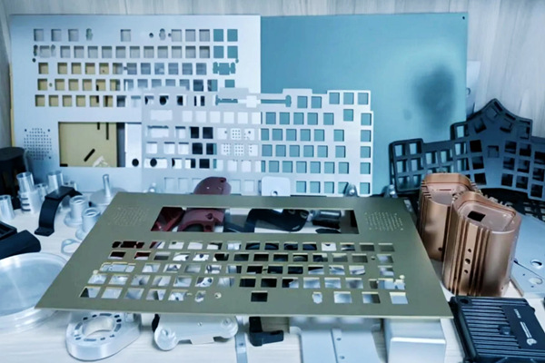
In the high-stakes arena of modern product development, the mantra "fail fast, fail cheap" has become a sacred text. Yet, while 3D printing and CNC machining often dominate the conversation around rapid prototyping, a quieter, more resilient workhorse is quietly revolutionizing the validation phase: the sheet metal framework component. Far from being a mere vestige of traditional manufacturing, sheet metal—when paired with advanced rapid prototyping techniques like laser cutting, CNC punching, and press braking—has emerged as an indispensable bridge between digital concept and physical reality. For products ranging from keyboard chassis to industrial controller housings and ventilated equipment racks, sheet metal parts offer a unique confluence of mechanical integrity, thermal realism, and geometric accuracy that plastic or resin prototypes simply cannot replicate. This article explores why sheet metal frameworks are not just beneficial but essential for meaningful engineering validation, ensuring that the path to market is paved with data, not guesswork.
The Material Truth: Why Plastic Isn't Enough
The fundamental limitation of additive manufacturing (AM) or urethane casting in prototype validation lies in the material properties. A stereolithography (SLA) resin or fused deposition modeling (FDM) plastic part can look like a finished product, but it cannot feel like one in terms of structural response. When an engineer needs to test the torsional rigidity of a laptop keyboard frame, the modulus of elasticity of a plastic prototype is often an order of magnitude lower than that of the intended aluminum or steel. Consequently, a bending test on a plastic frame will yield misleading data, potentially causing engineers to over-engineer the final product or, worse, miss critical resonance frequencies.
Sheet metal rapid prototyping circumvents this cognitive dissonance. By using the actual production-grade material—typically aluminum 5052, 6061, or cold-rolled steel—from the very first physical iteration, engineers obtain true-to-life data on stiffness, yield strength, and vibration damping. For a keyboard framework, this is paramount. The tactile feedback of a keyboard is not just about the switches; it is heavily reliant on the flexural rigidity of the mounting plate. A sheet metal prototype allows design teams to measure the "bounce" and "give" of the frame under keystroke loads, ensuring that the final product does not feel flimsy or, conversely, overly rigid. This material fidelity enables accurate Finite Element Analysis (FEA) correlation, closing the loop between simulation and reality.
Thermal Management: The Forgotten Variable in Enclosure Testing
In the development of controller housings for power electronics or server racks, thermal management is the axis upon which reliability turns. Plastic prototypes are notoriously poor thermal conductors. They act as insulators, trapping heat and forcing electronic components to throttle prematurely during stress tests. This creates a validation blind spot: a design that passes thermal tests with a plastic housing may catastrophically fail when switched to a metal enclosure due to different heat sink mounting pressures or unintended thermal pathways.
Sheet metal framework components, conversely, provide an authentic thermal simulation environment. When testing an industrial controller housing, the aluminum or steel prototype dissipates heat exactly as the production unit will, allowing engineers to verify the efficacy of venting patterns, the thermal interface between the housing and the heat sink, and the convective airflow paths. For instance, a prototype with louvers or perforations—rapidly produced via CNC punching—can be tested thermodynamically to measure pressure drops and air velocity. If the enclosure is designed to act as a passive heat sink, the sheet metal prototype validates the surface area and emissivity requirements. This level of empirical validation ensures that the product’s thermal regulation is sound before tooling investments are made, preventing costly heat-related redesigns late in the production cycle.
Geometric Precision and the "Fit" Challenge
The "digital twin" may align perfectly on a screen, but the physical world is governed by tolerances. In the realm of equipment frames—particularly the open, skeletonized frameworks used in audio-visual racks or telecommunication chassis—the precision of mounting holes, slot positions, and edge distances is critical. These frameworks serve as the structural "skeleton" onto which PCBs, power supplies, and cable management systems are attached. A misalignment of even 0.2mm in a mounting hole pattern can render a system assembly impossible or create undue stress on connectors.
Modern sheet metal prototyping employs high-precision laser cutting systems capable of holding tolerances within ±0.1mm. This allows engineers to perform "real-world" fit checks early in the design cycle. For a 19-inch rack chassis, the sheet metal framework prototype is not just a visual mock-up; it is a functional assembly jig. Designers can load the actual PCB assemblies, install the backplane connectors, and test the insertion/extraction forces of the modules. This rapid verification of hole alignments, slot depths, and bend radii ensures that the final stamped parts will mate seamlessly with purchased components. Furthermore, the ability to quickly modify a CAD file and cut a new framework within 24 hours allows for multiple iterations of fit testing, a luxury not afforded by slow, expensive injection molding or die-casting tools.
Structural Integrity Under Dynamic Loads
While plastic prototypes are adequate for static display, they fail miserably when subjected to drop tests, vibration tables, or shock testing. Equipment frames and portable device housings must survive shipping and operational abuse. The yield strength of a sheet metal prototype provides a realistic benchmark for crashworthiness. For example, in handheld controller housings, the frame often acts as the structural "backbone," protecting the internal display and battery.
By employing sheet metal prototyping, engineers can conduct destructive tests to find the ultimate failure point. They can analyze the deformation patterns to determine if the material gauge is sufficient or if the bend reliefs need adjustment. The data collected from these tests—such as load-deflection curves and fracture points—is directly translatable to the production process. Because the prototype and the final production part are made from the same starting material, the only variable between the prototype and the mass-produced component is the forming tool (press brake vs. stamping die). Therefore, the structural data obtained from the prototype is highly predictive of production performance, reducing the need for a "second round" of validation after tooling is complete.
The Accelerated Design Loop: "Cut, Bend, Test, Repeat"
The operational magic of sheet metal rapid prototyping lies in its compatibility with 2D and 3D CAD workflows. With the advent of automated nesting software and CNC turret punch presses, the lead time for a complex framework has shrunk from weeks to days—sometimes hours. This rapid turnaround fosters a culture of empirical experimentation. Instead of debating aerodynamic flow theories or structural load paths in meetings, engineers can physically test two or three variations of a framework component simultaneously.
Consider the development of a ventilated server rack frame. The team might test a variant with 30% open area using circular holes, a second variant with 40% open area using hexagonal perforations, and a third with variable slot sizes. All three can be fabricated, painted, and assembled onto the same base chassis within a single week. Subsequent testing for EMI/EMC shielding effectiveness, airflow, and structural rigidity provides unambiguous data to select the optimal design. This "test everything" methodology collapses the traditional design cycle, allowing product upgrades to be executed with a speed that matches the pace of software development.
Bridging the Gap to Production
Perhaps the most underrated advantage of using sheet metal frameworks in prototyping is the "production-readiness" of the design. Because the prototype is manufactured using the same material and similar processes (laser cutting, tapping, and welding) as the final product, the transition to hard tooling is smooth. Issues such as weld spatter, galvanic corrosion between dissimilar metals, and thread stripping torque are identified and resolved during the prototyping phase. This proactive problem-solving mitigates the risk of "tooling surprises," ensuring that the project stays on schedule and on budget.
In conclusion, while additive manufacturing remains a powerhouse for conceptual modeling and complex geometry, the sheet metal framework component is the definitive tool for engineering validation. Its ability to provide authentic structural, thermal, and assembly data makes it the gold standard for refining designs in the critical phase between concept and launch. For keyboard frames requiring tactile fidelity, controller housings demanding thermal accuracy, and equipment racks necessitating structural perfection, sheet metal prototyping is the silent accelerator of innovation. It ensures that by the time a product reaches the market, it has already survived the ruthless scrutiny of physics, not just the optimism of the CAD screen. In the relentless pursuit of better products, faster, sheet metal remains the trusted medium through which ideas are forged into reality.




