

Rapid Sheet Metal Prototyping for Aerospace Actuation Systems
In the high-stakes world of aerospace engineering, the gap between a digital blueprint and a flight-ready component is often measured in microns and milliseconds. When a mid-tier aerospace supplier faced a critical bottleneck in developing a new electro-mechanical actuation system for unmanned aerial vehicles (UAVs), they turned not to a traditional machine shop, but to a specialized provider of rapid sheet metal services. The challenge was not merely about speed; it was about achieving geometric fidelity and metallurgical integrity in a compressed timeline, a test of both machine capability and human expertise.
The component in question was a complex, multi-bend housing bracket for a flap actuator. The original design called for a machined billet of 7075-T6 aluminum, a process with a lead time of six weeks and a material removal rate exceeding 80%. This approach was not only cost-prohibitive but also wasteful. The engineering team proposed a radical shift: converting the design to a fabricated sheet metal assembly. However, the new design featured tight tolerance pockets, a 1.5mm wall thickness, and four intersecting bend axes that required a forming accuracy of±0.1mm to ensure proper bearing alignment. Traditional stamping was out of the question due to the low volume and the geometric complexity; thus, the project defaulted to rapid sheet metal fabrication.
Upon receipt of the STEP files, the service provider initiated a rigorous Design for Manufacturability (DFM) analysis. This was not a cursory check for hole sizes or bend radii. It was a deep, parametric interrogation of the model. The lead engineer identified a critical stress concentration at the intersection of two flanges, a point where the K-factor of the bend would inevitably cause material thinning. Using specialized unfolding software, the team simulated the bend sequence, predicting a 12% elongation on the outer fiber. Rather than increasing the material gauge—which would have added unnecessary weight—they offset the neutral axis in the flat pattern by 0.08mm. This microscopic adjustment, invisible to the naked eye, ensured that the final part would meet the dimensional envelope without post-bend machining.
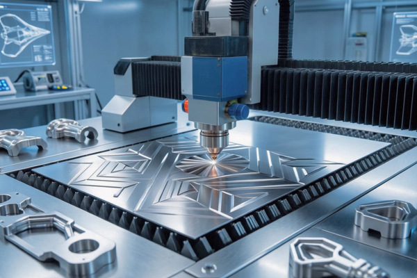
The real mastery, however, unfolded on the shop floor. The process began with a high-speed fiber laser cutter operating at 4kW. Unlike CO2 lasers, which can struggle with reflective materials, the fiber laser delivered a focused beam that minimized the heat-affected zone (HAZ). Cutting 7075-T6, known for its susceptibility to stress cracking, requires a delicate balance of feed rate and assist gas pressure. The technician adjusted the nitrogen purge to 16 bar, a setting that prevented oxidation while ensuring a dross-free edge. The resulting burr was less than 0.02mm, effectively eliminating the need for secondary deburring, which often introduces geometric drift.
The forming stage was the crux of the operation. The shop relied on a 135-ton CNC press brake equipped with a six-axis backgauge and a sophisticated crowning system. The part required three sequential bends, but the orientation of the fourth bend posed a problem: the flange was too narrow for standard tooling. The solution was a custom-ground punch with a 0.8mm radius tip, fabricated in-house from powdered high-speed steel. The operator programmed an“air bending”sequence, where the punch does not bottom out against the die. This technique allows for greater springback compensation—specifically, an over-bend of 1.5 degrees to account for the elastic recovery of the aluminum. The press brake’s real-time angle measurement probes verified each bend within milliseconds, adjusting the ram pressure dynamically to counteract any variations in material hardness.
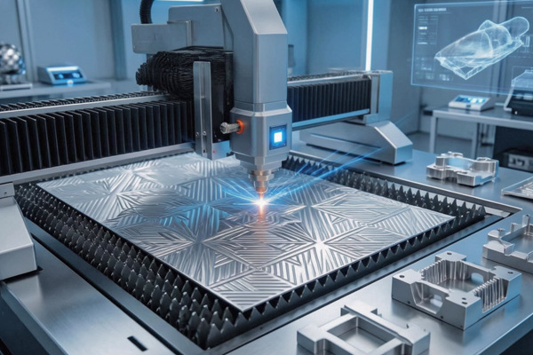
Post-forming, the part entered the inspection phase, but here the rapid aspect shifted from production to validation. A traditional coordinate measuring machine (CMM) would have taken four hours to map the complex surfaces. Instead, the shop employed a structured-light 3D scanner that projected blue-light patterns onto the bracket. Within sixty seconds, the software generated a million-point cloud, comparing the physical object to the nominal CAD model. The resulting color map showed deviations of only +0.06mm at the critical bearing pocket, well within the acceptable tolerance. Interestingly, the scanner revealed a slight twist along the longitudinal axis, a distortion invisible to the naked eye. The root cause was traced to residual stress relief during laser cutting. To correct this, the technician performed a corrective twist-bending operation using a manual arbor press with a dial indicator, applying a corrective torque of only 4 Nm. This "tactile" correction, based on years of empirical intuition, salvaged the part that the software predicted would be rejected.
The final stage was a secondary surface enhancement. Rather than anodizing, which can alter critical dimensions by introducing a 25-micron layer, the team applied a chemical conversion coating (Alodine) followed by a PTFE-impregnated lubricant. This provided the necessary corrosion resistance without compromising the tight clearances. The entire run of 25 pieces, from raw coil stock to packaged components, was completed in 36 operational hours—a 75% reduction compared to the original machining route. The cost per unit decreased by 62%, and the material utilization improved from 20% to 89%.
This case exemplifies that rapid sheet metal services are not a concession to quality in exchange for speed. Rather, they represent a synthesis of predictive simulation, adaptive machine control, and the irreplaceable judgment of seasoned craftsmen. The success rested on the technician’s ability to read the grain flow of the metal, the programmer’s foresight in offsetting the neutral axis, and the inspector’s trust in optical metrology over physical touch probes. In an industry where every gram and every micron counts, the ability to iterate physically as fast as one iterates digitally is the new benchmark of manufacturing excellence.




